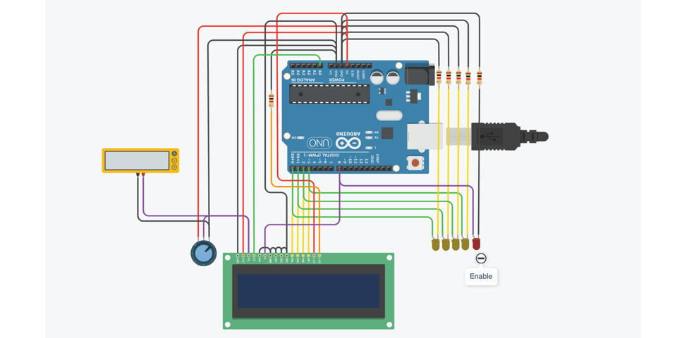
Tinkercad-LCD without any library

The HD44780 is a popular controller chip used in alphanumeric liquid crystal display (LCD) modules. Developed by Hitachi, it’s widely used in various electronic devices such as consumer electronics, industrial equipment, and hobbyist projects.
The HD44780 chip simplifies the process of interfacing with a character LCD. It handles tasks such as generating the signals needed to display characters on the screen, managing the cursor position, and handling input/output operations. By using this controller, developers can communicate with the LCD using a relatively simple set of commands and connections, making it easier to integrate displays into their projects.
These displays typically have a fixed number of characters and are commonly used to display text-based information, such as in digital clocks, small appliances, and electronic instruments. They are relatively low-cost, easy to use, and consume minimal power, making them a popular choice for embedded systems and hobbyist projects.
Usually it controlled with LiquidCrystal Arduino library. The LiquidCrystal library is a library for Arduino and compatible microcontroller platforms that simplifies the process of interfacing with liquid crystal displays (LCDs) that use the Hitachi HD44780 (or a compatible) controller chip.
But we will do it without any library to demonstrate how it is working behind the scenes.
#define DELEAY 2
#define DATAMODE 0b0010 // 4 bit data mode

// CLEAR Command
#define CLEAR_1 0b0000
#define CLEAR_2 0b0001

// ON Command
#define ON_1 0b0000
#define ON_2 0b1100

// Char H
#define H_1 0b0100
#define H_2 0b1000

// Char I
#define I_1 0b0100
#define I_2 0b1001

void setup()
{
  DDRD = B11111111; // set PORTD (digital 7~0) to outputs
  DDRB = B11111111; // set PORTB (digital 7~0) to outputs
  DDRC = B11111111; // set PORTC (digital 7~0) to outputs
}

void loop()
{
  command(DATAMODE);

  command(ON_1);
  command(ON_2);
  while(1)
  {
    command(CLEAR_1);
    command(CLEAR_2);

    ch(H_1);
    ch(H_2);

    ch(I_1);
    ch(I_2);
  }
}

void command(int command)
{
  PORTC = B0;
  PORTD = command;
  PORTB = B1;
  delay(DELEAY);
  PORTB = B0;
}

void ch(int ch)
{
  PORTD = ch;
  PORTC = B1;
  PORTB = B1;
  delay(DELEAY);
  PORTB = B0;
}
This code is for controlling an LCD display in 4-bit mode using an Arduino or a similar microcontroller. The LCD display is assumed to be connected to the microcontroller’s digital pins.
Here’s a breakdown of the code:
Definitions:
    DELEAY: Defines the delay duration used in the delay() function calls.
    DATAMODE, CLEAR_1, CLEAR_2, ON_1, ON_2: These are predefined constants representing various commands and control signals for the LCD.
    H_1, H_2, I_1, I_2: Word `HI`, each character is splitted by half to send in 4-bit mode.
    B0, B1, B11111111: There file in arduino that have all binary constants defined from 0 to 255, like that #define B11110000 240

setup() function:
    Sets the data direction register (DDR) for ports D, B, and C to make all digital pins outputs. This prepares the microcontroller's pins to send signals to the LCD.

loop() function:
    Sets the data mode to 4-bit mode using the DATAMODE command.
    Turns on the display by sending the ON_1 and ON_2 commands.
    Enters an infinite loop:
        Clears the display by sending the CLEAR_1 and CLEAR_2 commands.
        Writes characters "HI" to the display.

command() function:
    Accepts a command as an integer parameter.
    Sets the RS (Register Select) pin to 0 (indicating a command).
    Sends the command to the LCD by setting the appropriate values on the data pins (port D) and toggling the Enable (EN) pin.

ch() function:
    Accepts a character (ASCII value) as an integer parameter.
    Sets the RS pin to 1 (indicating data).
    Sends the character to the LCD by setting the appropriate values on the data pins (port D) and toggling the Enable (EN) pin.
Reference
- Reading a datasheet https://www.youtube.com/watch?v=cXpeTxC3_A4
- Peter Ouwehand has written an excellent article describing how to use the HD44780 https://www.ekenrooi.net/lcd/lcd.shtml
- Creating custom characters https://www.quinapalus.com/hd44780udg.html