PCF8574
To control a 7-segment display using a PCF8574 I/O expander and an Arduino, you need to map each segment of the display to the corresponding pins of the PCF8574. Then, you can write code that efficiently controls the segments to display numbers or characters.
Components Required:
- Arduino (any model)
- PCF8574 I/O expander
- 7-segment display (common cathode or common anode)
- Jumper wires
- Breadboard (optional)
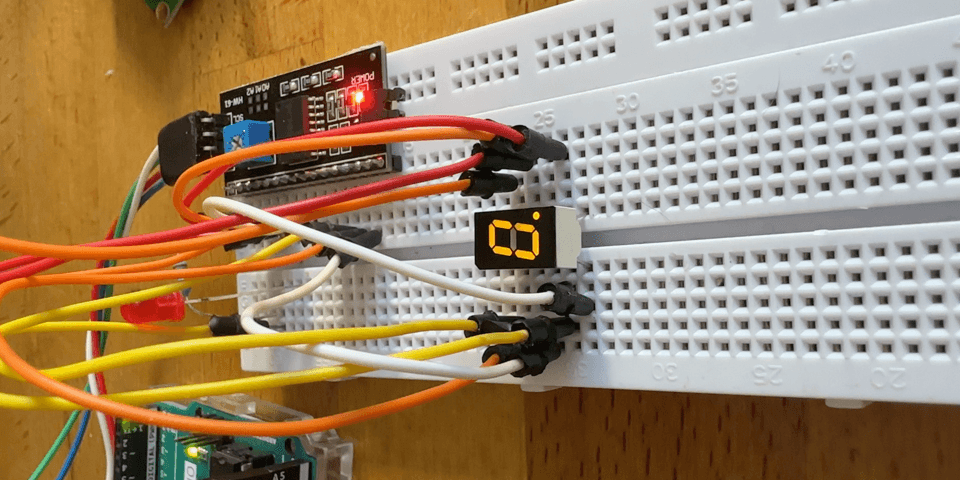
Step 1: Wiring
- Connect the PCF8574 to the Arduino:
- SDA (PCF8574) to SDA (Arduino, usually A4 for Uno)
- SCL (PCF8574) to SCL (Arduino, usually A5 for Uno)
- VCC and GND to 5V and GND on the Arduino.
- Connect the PCF8574 to the 7-segment display:
- Connect each segment (A to G and DP) of the 7-segment display to the PCF8574. For example:
- Segment A → P0 (PCF8574)
- Segment B → P1 (PCF8574)
- …
- Segment G → P6 (PCF8574)
- Decimal Point (DP) → P7 (PCF8574) (optional) The pin configuration will depend on your specific display.
       +----------------+               +-------------------+               +----------------------+
|   Arduino      |               |      PCF8574      |               |  7-Segment Display   |
|                |               |                   |               |                      |
|   5V           |---------------| VCC               |               |                      |
|   GND          |---------------| GND               |---------------| GND                  |
|   A4 (SDA)     |---------------| SDA               |               |                      |
|   A5 (SCL)     |---------------| SCL               |               |                      |
|                |               |                   |               |                      |
|                |               |               P0  |---------------| Segment A            |
|                |               |               P1  |---------------| Segment B            |
|                |               |               P2  |---------------| Segment C            |
|                |               |               P3  |---------------| Segment D            |
|                |               |               P4  |---------------| Segment E            |
|                |               |               P5  |---------------| Segment F            |
|                |               |               P6  |---------------| Segment G            |
|                |               |               P7  |---------------| Decimal Point        |
+----------------+               +-------------------+               +----------------------+
Step 2: Arduino Code
Now, let’s write the Arduino code to control the 7-segment display using the PCF8574.
       #include <Adafruit_PCF8574.h>

/* Example for 16 output LEDs that are connected from power to the GPIO expander pins
 * Note the LEDs must be connected with the CATHODES to the expander, to SINK current!
 * The PCF8574 cannot SOURCE current!
 */

Adafruit_PCF8574 pcf;

void setup() {
  while (!Serial) { delay(10); }
  Serial.begin(115200);
  Serial.println("Adafruit PCF8574 LED blink test");

  if (!pcf.begin(0x27, &Wire)) {
    Serial.println("Couldn't find PCF8574");
    while (1)
      ;
  }
  for (uint8_t p = 0; p < 16; p++) {
    pcf.pinMode(p, OUTPUT);
  }
//displayDigit(0);
}
// HIGH is 0ff
// Map each digit (0-9) to its corresponding 7-segment binary pattern
const uint8_t digitMap[10] = {
  0b00111111,  // 0
  0b00000110,  // 1
  0b01011011,  // 2
  0b01001111,  // 3
  0b01100110,  // 4
  0b01101101,  // 5
  0b01111101,  // 6
  0b00000111,  // 7
  0b01111111,  // 8
  0b01101111   // 9
};
void loop() {

  for (int i = 0; i < 10; i++) {
    displayDigit(i);  // Display the digit 0 to 9 in sequence
    delay(1000);      // Wait 1 second between each digit
  }
}

const uint8_t segmentPins[8] = {0, 1, 2, 4, 5, 6, 7, 8}; // A to DP

// Function to display a digit on the 7-segment display
void displayDigit(int digit) {
  uint8_t segments = digitMap[digit];

  for (int i = 0; i < 8; i++) {
    pcf.digitalWrite(segmentPins[i], (segments & (1 << i) ? LOW : HIGH));
  }
}
Explanation:
digitMap: This array contains the binary patterns for each digit (0-9). Each bit in a byte represents a segment on the 7-segment display. A bit value of 1 means the segment is on, while 0 means it is off.displayDigit: This function takes a digit (0-9) as input and turns on/off the corresponding segments on the display by writing to thePCF8574pins.- Common Anode/Cathode: The code assumes a common anode 7-segment display. If you are using a common cathode display, you need to reverse the logic in the
displayDigit()function (i.e., changeLOWtoHIGHand vice versa).
Additional Features
- Display Multiple Digits: You can extend the code to handle multiple 7-segment displays by using a multiplexing technique or by adding more PCF8574 expanders.
- Display Letters: You can add more patterns to the digitMap array to display certain letters.
This setup and code provide an efficient way to control a 7-segment display using the PCF8574 I/O expander with minimal I/O pin usage on the Arduino.